SLM Lab Practicum

Read through all linked materials below!
The Prequel: Before doing any lab work this week, you need to have completed your analysis of last week's data taken with your particular SLM. See Piazza Note @43. Your completed analysis belongs in your OneNote
Part 1) Over the weekend, you were asked to think about the wavelength dependence of the retardance of a waveplate, which depends upon the ratio of its physical thickness to the wavelength of the light used, but you must keep in mind that the wavelength inside the liquid crystal material depends upon how the index of refraction varies as a function of frequency. (The retardance also depends upon the angle of incidence, as that affects the path length) First, make a prediction for the maximum phase throw you expect to find when you move to a specific different wavelength, corresponding to
low-energy photons. Only once you have your clearly written predictions entered into OneNote can you proceed to test your predictions, and to record your subsequent celebrations in OneNote.
Part 2) If "flipped" very carefully a flip mirror allows you to flip back and forth between two optical inputs and still be in alignment. With that in mind, carefully return (for now) to your previous set-up, using the same wavelength as last week.
From your analysis of last week's data taken with your particular SLM, you should be able to calculate the "grayscale levels" needed for your SLM to toggle between acting as a waveplate with retardances of 0, λ/4, λ/2, 3λ/4, and 1. Your OneNote should make it clear that you really can do this.
Does this allow you to toggle a laser beam between polarization basis states of: +45, -45, H, V, L, R ? If not, why not? Where possible, test your results in the same manner that you did when you used a "real" waveplate. Your OneNote should clearly show your lab work, and your conclusions.
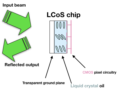
Part 3) At most stations in our lab, the SLMs make use of un-twisted liquid crystals. For those, unlike the (less expensive) twisted liquid crystals found in common commercial devices (such as classroom displays), it is possible to make adjustments such that the polarization state of the beam entering the SLM is aligned with the extraordinary direction of the SLM. (Such a polarization state is said to be an eigenstate of the Mueller Matrix.) For such an input state, an ideal SLM would no longer act to change the polarization state, but it would still allow pixel-by-pixel adjustment of
local time lags. With your output analyzer removed, you should try to find an input polarization that maximizes this behavior (e.g., by "displaying" a pattern that should, for a pure phase modulator, behave like a simple prism). Once your input polarization state has been optimized, then re-insert and adjust the output analyzer to suppress light not associated with pure phase modulation. At that point, ideally, your combined system (input state preparation + SLM + output analyzer) would be set up to provide pixel-by-pixel "phase-only modulation," instead of producing the "amplitude modulation" you studied last week.
Read my SLM code for adding, to a laser beam, "ORBITAL" angular momentum (OAM), by encoding a "sprial phase profile" (MODULO 2π). This code can be read by any word-processing program, and you may treat it as pseudo-code meant to inspire your own program, but it will actually run using the programming language IDL, or its open-source equivalent, GDL. Include the /circ keyword for all of your work for today. The keyword /maxGSL should be set to π/B, where B is the fitting parameter you found last week, for this particular wavelength.
You should begin your lab tests by addressing the SLM with phase profiles where the radial mode number is zero, and the azimuthal mode number is large (e.g., 50).
Can you find (and capture an image of) the first-order "donut beam"?
Your OneNote should:
-
Systematically explore the beams you can create with my SLM code (or your own version of it), both showing and discussing the trends seen in your lab results as you vary the azimuthal mode number, and then as you vary the radial mode number
-
Explain the utility of the "blazing" (perhaps after exploring what happens if you reduce, from the default setting, the number of blazing present)
-
Explain why the radial lines seen with /noblaze are NOT discontinuities
-
Explain why a singular point where all phases meet must yield a locally dark region in the output beam
Your work will be graded as a "Lab Practicum"!

